QA007/QA008/QA009 ESP32 Max V1.0 Controller Board
1.Introduction
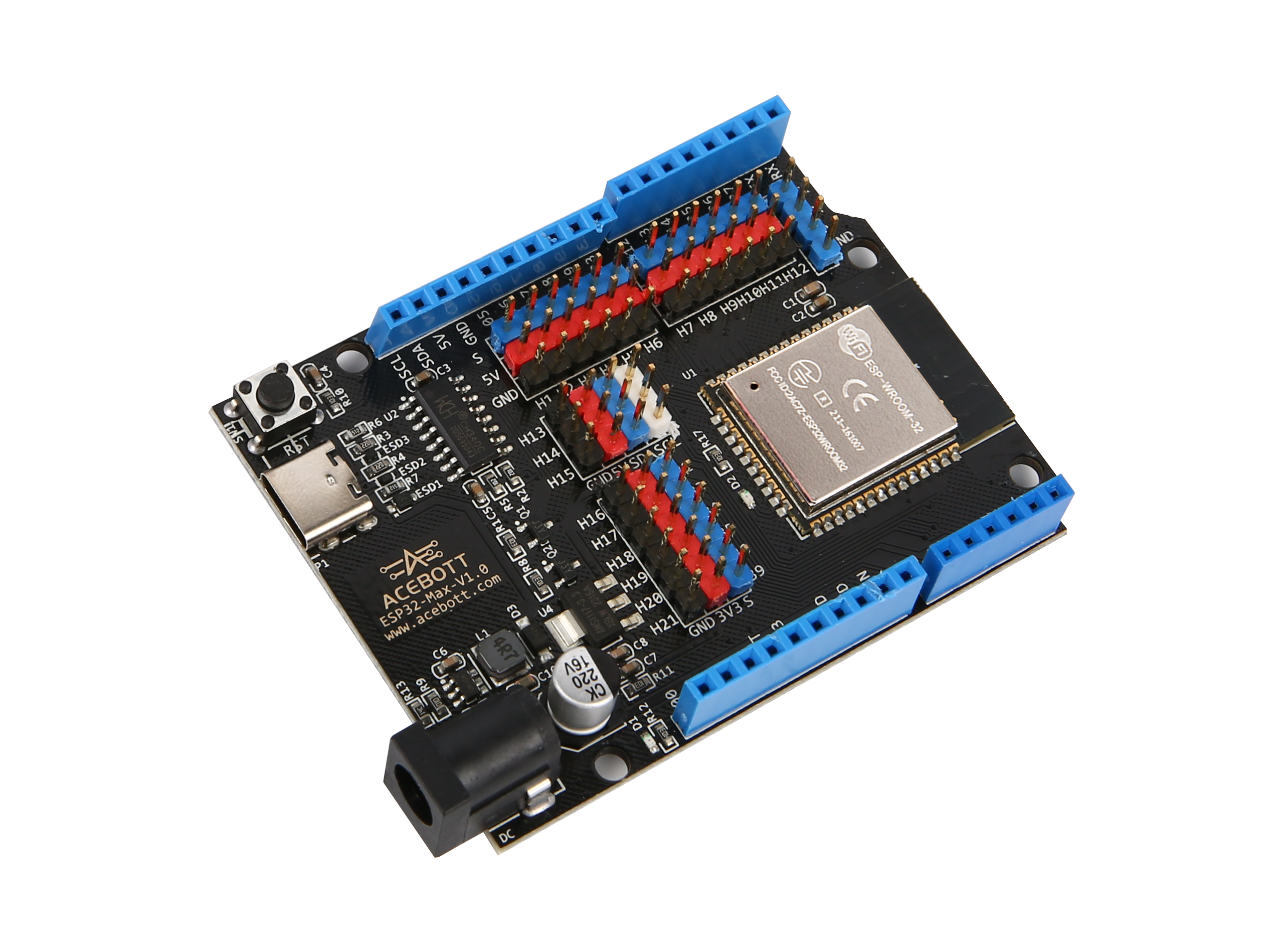
The ESP32 Max 1.0 controller board is a low power consumption, high performance microcontroller, very suitable for the development of the Internet of Things.
It has a 240 MHz dual-core processor, 520 KB of RAM, and 4MB of flash memory. Built-in WiFi and Bluetooth 4.2 module, available for wireless communication. With 34 GPIO ports, it can connect and control various peripherals.
If you want to know more about ESP32, click here
2.Features
1.Upgrade Type-C interface for stronger compatibility
2.IO pins are all exported to facilitate development
3.No extra breadboard is needed. It has male and female pins, and the pins are clearly colored for easy wiring
4.The Type-C interface is equipped with an electrostatic discharge protection diode and a transient voltage suppression diode to protect the chip from electrostatic breakdown and damage from various surge pulses
3.Specifications
Connectivity |
WI-FI | Bluetooth LE |
|---|---|
Chip |
ESP-WROOM-32 |
Clock |
240MHz |
ROM |
448KB |
SRAM |
520KB |
FLASH |
4MB |
Interfaces |
UART | I2C | SPI | CAN |
Input Voltages |
6-18V |
Pinout |
25(DIGITAL) | 15(ANALOG)| 25(PWM) | 2(DAC) | 2(UART) | 2(SPI) | 1(I2C) |
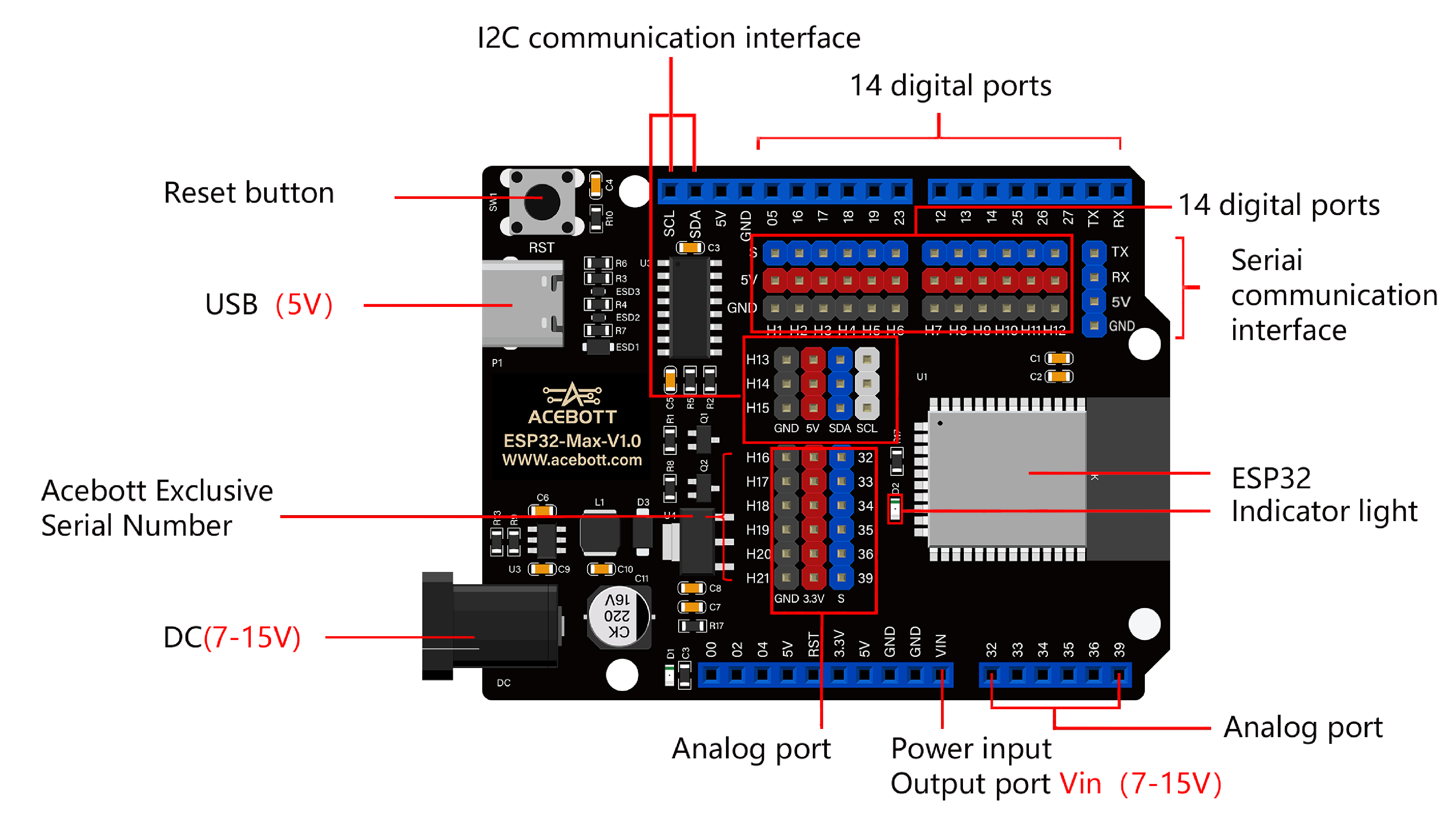
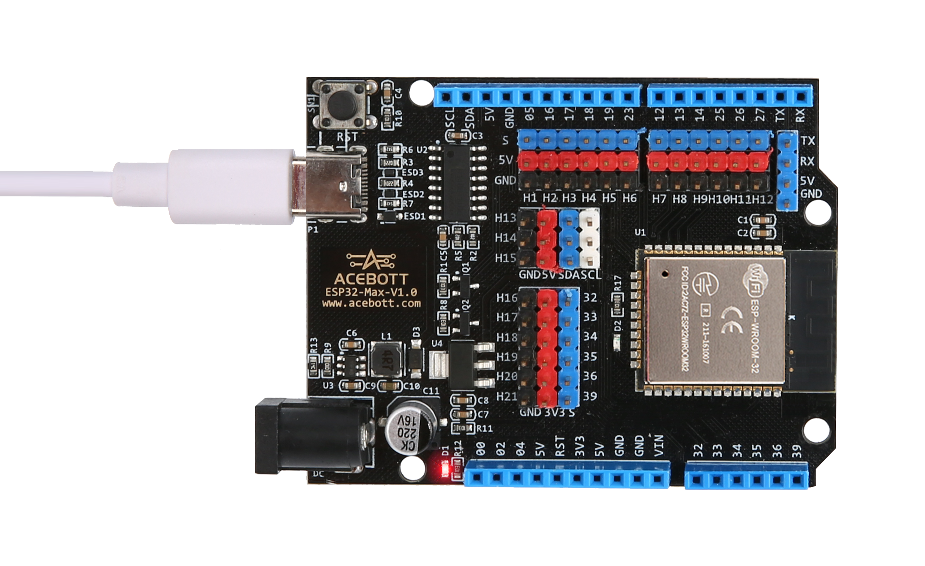
4.PCB Description
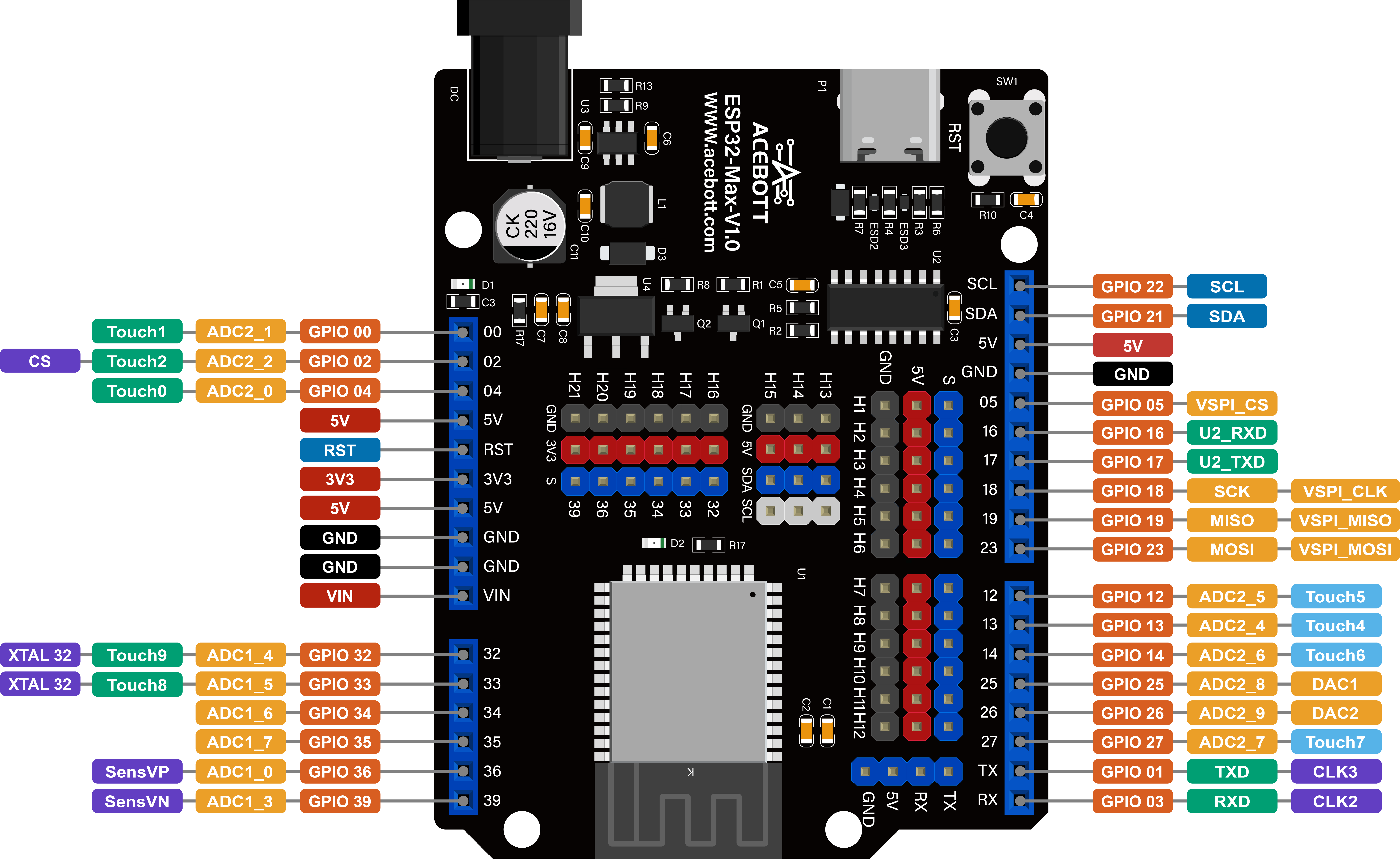
The figure illustrates the GPIO pins and the corresponding functions of the ESP32 Max 1.0 controller board, including ADC, DAC, PWM, I2C, SPI pins, etc.
Only Input Pin: GPIO 34/GPIO 35/GPIO 36/GPIO 39
Default I2C Pin: GPIO 21(SDA)/GPIO 22(SCL)
DAC Pin: GPIO 25(DAC1)/GPIO 26(DAC2)
5.Note
(1)The ADC2 pin cannot be used when using Wi-Fi. Therefore, if you can’t get the value from the ADC2 GPIO on Wi-Fi, consider using the ADC1 GPIO instead.
(2)The ADC input channel has 12-bit resolution. This means that you can get analog readings between 0 and 4095, where analog value 0 corresponds to 0V and analog value 4095 corresponds to 3.3V. You can also set the resolution of the channel as well as the ADC range on the code.
(3)ESP32 ADC pins do not have linear behavior. You might not be able to distinguish between 0 and 0.1V, 3.2 and 3.3V, be aware of this when using ADC pins and you will get a data image similar to the one shown below.

6.Detailed Use with ARDUINO Software as follows:
Step1 | Download the Arduino environment (IDE)
Step2 | Install the ESP32 plugin in the Arduino IDE
Step3 | Download CH340 Driver
Step4 | Upload the LED lighting program
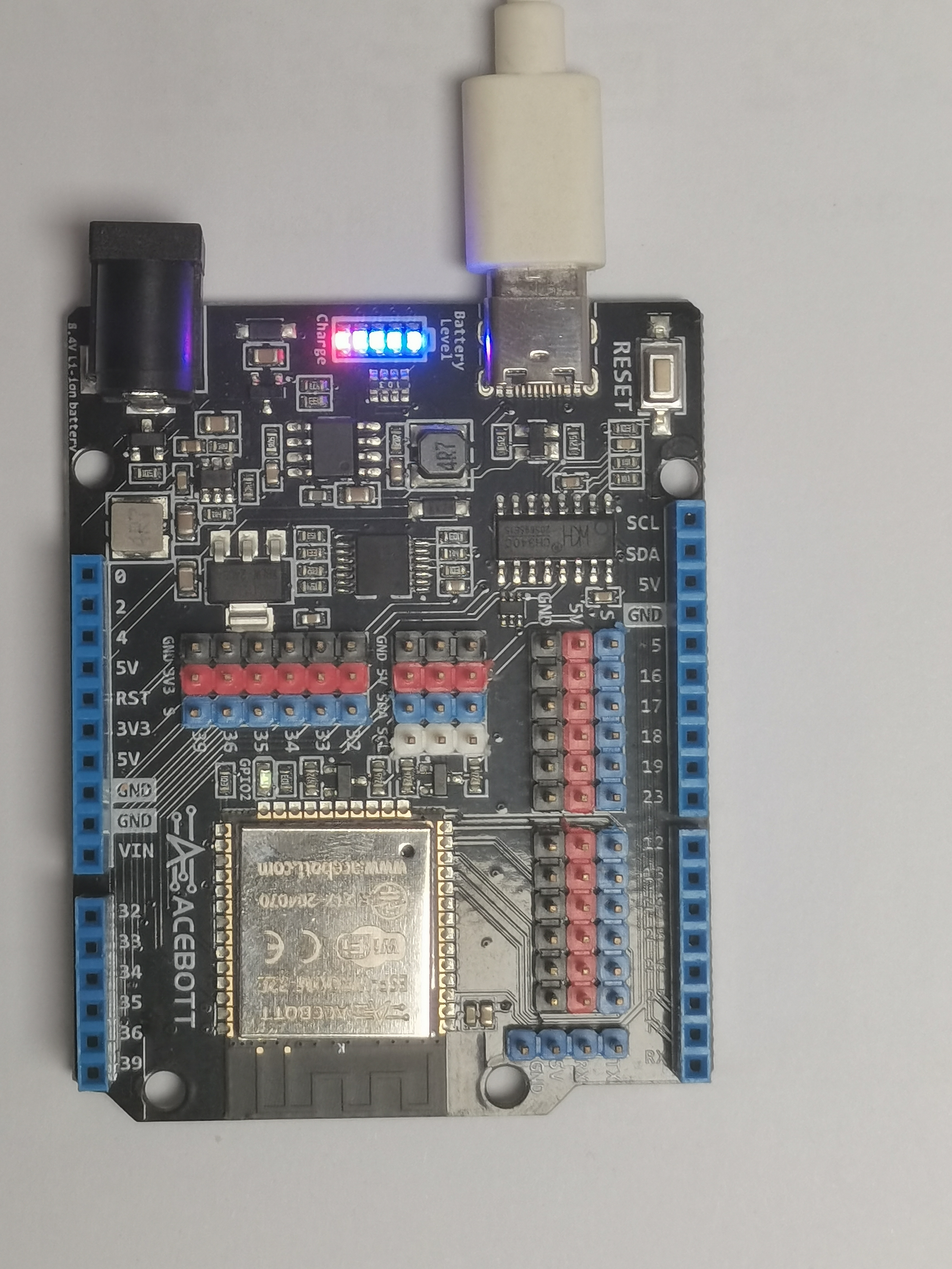
Connect the board to the computer using a Type-C data cable.The red power LED should go on.
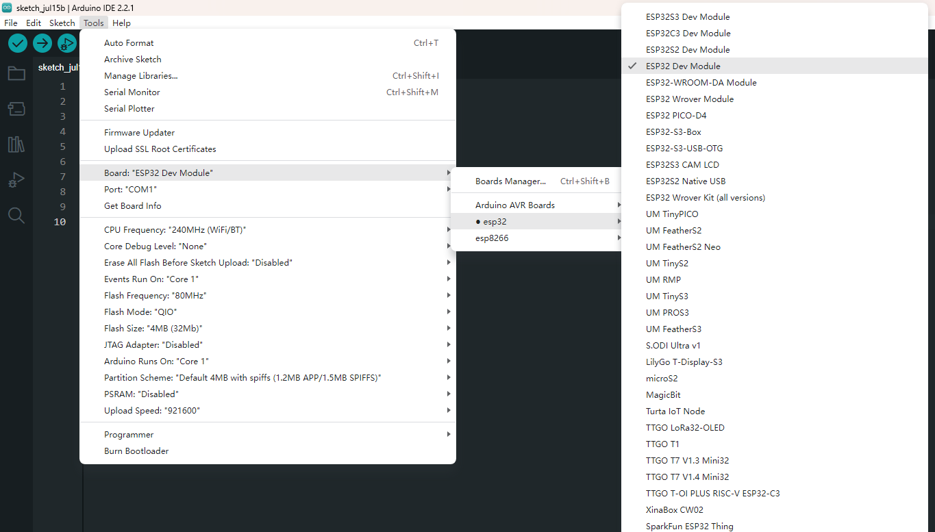
Select “ESP32” -> “ESP32 Dev Module” from the Tools > Board menu
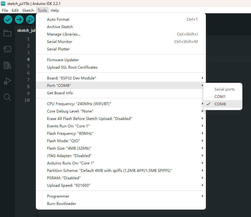
Select the serial device of the board from the Tools | Serial Port menu. This is likely to be COM8 or higher (COM1and COM2 are usually reserved for hardware serial ports). To find out, you can disconnect your board and re-open the menu; the entry that disappears should be the board. Reconnect the board and select that serial port. Here you should select COM 8 as below.
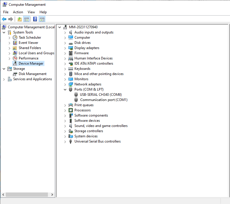
You also can find the right ports shown on Device Manager.
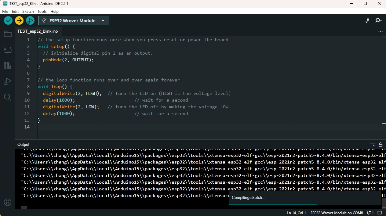
Upload the Program.
 1// the setup function runs once when you press reset or power the board
 2void setup() {
 3  // initialize digital pin 2 as an output.
 4  pinMode(2, OUTPUT);
 5}
 6
 7// the loop function runs over and over again forever
 8void loop() {
 9  digitalWrite(2, HIGH);  // turn the LED on (HIGH is the voltage level)
10  delay(1000);                      // wait for a second
11  digitalWrite(2, LOW);   // turn the LED off by making the voltage LOW
12  delay(1000);                      // wait for a second
13}
click the “Upload” button to upload the code. will appear in the status bar.
Wait a few seconds. If the upload is successful, the message “Done uploading.”
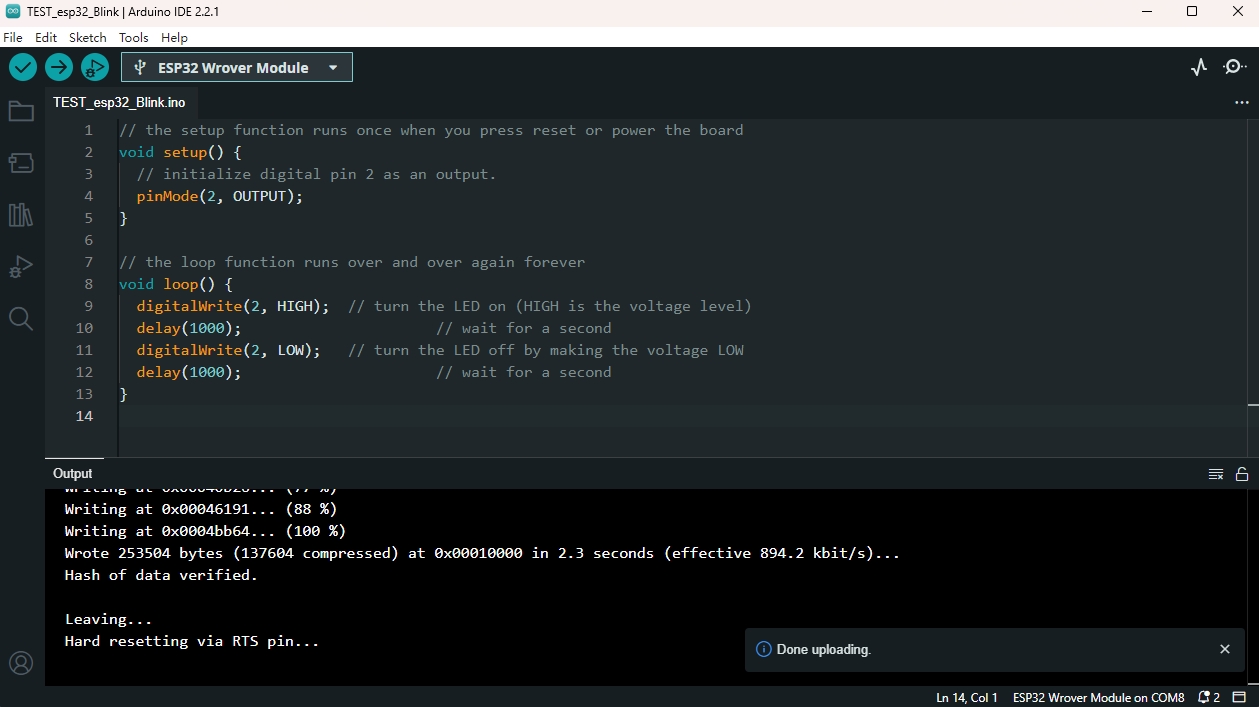
And the LED on the board blink.
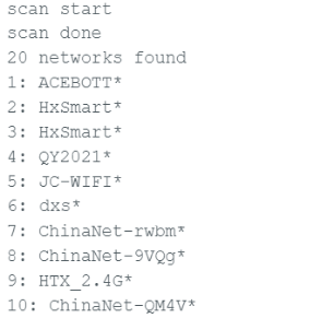
If your tests were successful, you can try to upload the following code. When a network is found in the environment, the number and name of all nearby networks will be obtained and displayed in the serial port, and the indicator will light up.
 1/*
 2When a network is found in the environment,
 3the number and name of all nearby networks will be obtained and displayed in the serial port,
 4and the blue indicator will light up.
 5*/
 6#include "WiFi.h"
 7void setup()
 8{
 9    Serial.begin(115200);
10    pinMode(02,OUTPUT);
11    //set WiFi to station mode and disconnect from an AP if it was previously connected
12    WiFi.mode(WIFI_STA);
13    WiFi.disconnect();
14    delay(100);
15    Serial.println("Setup done");
16}
17void loop()
18{
19    Serial.println("scan start");
20    // WiFi.scanNetworks will return the number of networks found
21    int n = WiFi.scanNetworks();
22    Serial.println("scan done");
23    if (n == 0) {
24        Serial.println("no networks found");
25    } else {
26        Serial.print(n);
27        Serial.println(" networks found");
28        digitalWrite(2, HIGH);//the blue indicator lights up
29        for (int i = 0; i < n; ++i) {
30            //print SSID and RSSI for each network found
31            Serial.print(i + 1);
32            Serial.print(": ");
33            Serial.print(WiFi.SSID(i));
34            Serial.println((WiFi.encryptionType(i) == WIFI_AUTH_OPEN)?" ":"*");
35            delay(10);
36        }
37    }
38    Serial.println("");
39    // wait a bit before scanning again
40    delay(5000);
41}
The serial port display effect diagram is as follows:
7.Package List
ESP32 Max V1.0 Controller Board * 1pcs
Type-C cable * 1pcs