QA017 ESP32 Shield V1.0
1.Introduction
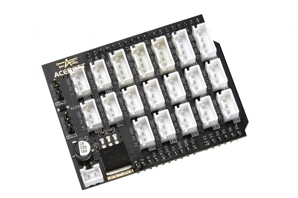
The ACEBOTT-ESP32-Shield-V1.0 is an expansion board for the ESP32-Max-V3.0 controller board. The expansion board adopts a standardized connection method, which simplifies the hardware connection process, can also reduce the wiring work of users, reduce the possibility of errors, and better help developers improve the development efficiency of the project.
For more information about the ESP32 controller board, please click the following link: https://acebottteam.github.io/acebott-docs-master/board/ESP32/QA007%20ESP32%20Max%20V1.0%20Controller%20Board.html
2.Features
Eight 3-pin digital pins for connecting 5V sensors/modules
Six 3-pin analog pins, four of which are connected to 5V sensors/modules and two to 3.3V sensors/modules
One 4-pin digital pin (two signal pins, one power, one GND)
One 4-pin digital pin (three signal pins, one GND)
Two rows with ESP32-Max-V3.0 pin interface
Two I2C pins
Two servo interfaces
One serial port
One power supply interface (output current of the maximum input voltage 15V 3A)
Operating temperature 0~70℃
3.Specifications
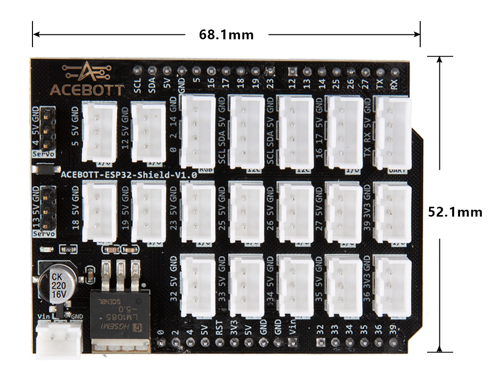
Size:68.1mm*52.1mm
Weight:22.1g
4.Sample Code
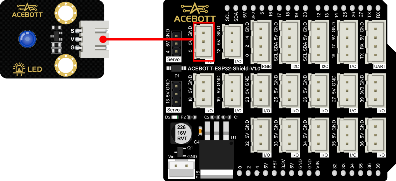
Connect the expansion board to the esp32 controller board, connect an LED light module in the No. 5 pin interface of the expansion board, upload program, control the opening and closing of the LED light.
(1)Wiring Diagram
(2)Sample Code
 1#define Led 5
 2
 3void setup(){
 4  pinMode(Led, OUTPUT);//Define the mode of the LED light
 5}
 6
 7void loop(){
 8  digitalWrite(Led,HIGH);//Turn on LED light
 9  delay(1000);
10  digitalWrite(Led,LOW);//Turn off LED light
11  delay(1000);
12}
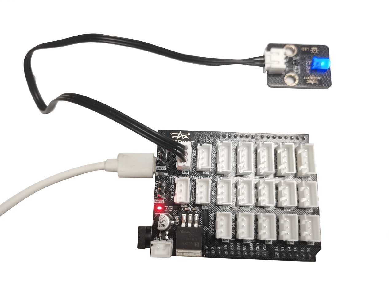
5.Test Result
After the program is uploaded, the LED lights achieve a cycle effect of flashing every second.
6.Related Resources