QA003 Mega 2560 R3 Development Board
1.Introduction
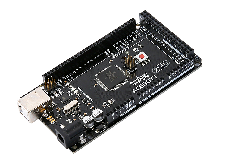
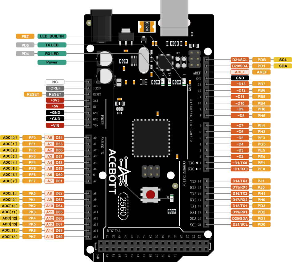
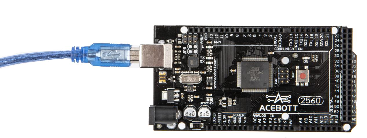
The ACEBOTT QA003 MEGA 2560 R3 development board is a micro controller board based on the ATMEGA2560, featuring 54 digital input/output pins, suitable for designs requiring a large number of IO interfaces. Its processor core is the ATmega2560, with 54 digital input/output pins (of which 15 can be used as PWM outputs), 15 analog inputs, 4 UART interfaces, a 16MHz crystal oscillator, a USB port, a power socket, an ICSP header, and a reset button. It includes everything the micro controller needs, and you can easily drive it by simply connecting it to the computer’s USB port, using an AC-DC adapter, or using batteries. Compared to the UNO, it provides more IO ports, and its form and function are almost compatible with the UNO.
2.Features
Micro controller: ATmega2560
Operating Voltage: 5V
Input Voltage (Recommended): 7-12V
Input Voltage (Limit): 6-20V
Digital I/O Pins: 54 (including 15 PWM outputs)
Analog Input Channels: 16
DC Current per I/O Pin: 40 mA
3.3V Port Output Current: 50 mA
Flash Memory: 256 KB (8 KB used by boot loader)
SRAM: 8 KB
EEPROM: 4 KB
Clock Speed: 16 MHz
3.Specifications
Parameters |
Value/Description |
|---|---|
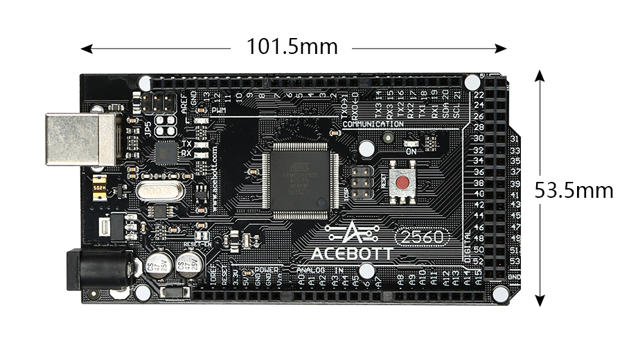
Size |
101.5X53.3(mm) |
Power supply |
Type-b |
Operating temperature |
10°C - 30°C |
Supported interfaces |
UART/GPIO/ADC/PWM/SPI/I2C |
Number of I/O ports |
54 |
PWM Channels |
15 |
Falsh |
256KB |
4.Sample Code
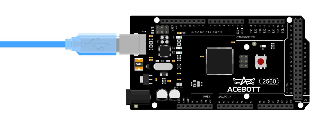
Connect the board to the computer using a USB data cable: Select “Arduino AVR Boards” -> “Arduino Mega or Mega 2560” from the Tools > Board menu. Choose the appropriate Port. And upload it to the board using the Upload button.
(1)Wiring Diagram
(2)Sample Code
1void setup() {
2  Serial.begin(9600);//The serial port baud rate is set to 9600
3}
4void loop() {
5  Serial.println("Hello,QA003 MEGA 2560 R3");
6  delay(1000);//Delay for 1 second.
7}
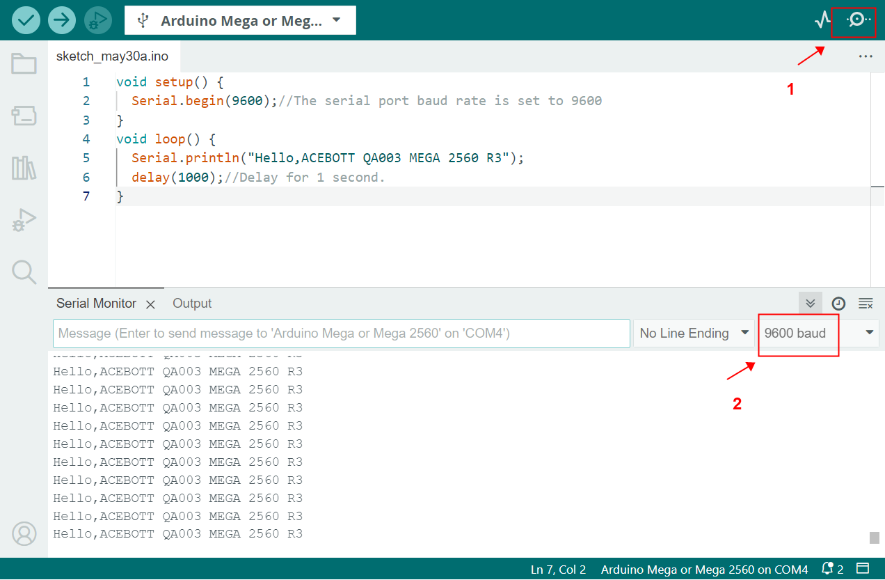
5.Test Result
After uploading the program, open the serial monitor in the Arduino IDE to observe the continuous serial printing of “Hello,ACEBOTT QA003 MEGA 2560 R3”.
6.Related Resources
7.Get One Now
B2B Business: info@acebott.com