QA001 UNO R3 Development Board
1.Introduction
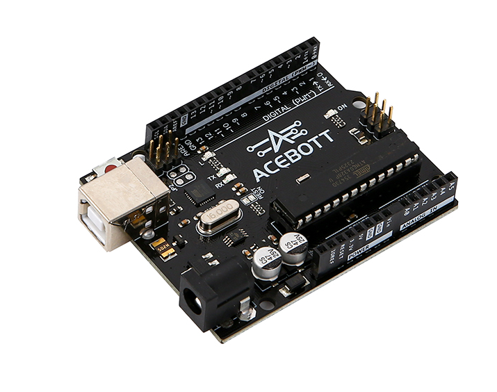
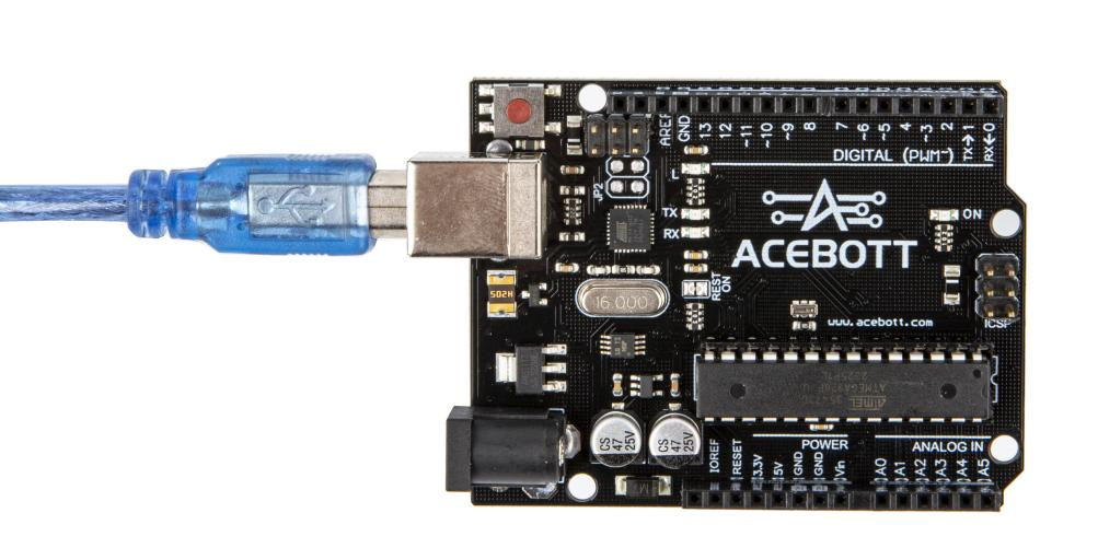
The ACEBOTT QA001 UNO R3 development board is a micro controller board based on ATMEGA328P. It features 14 digital input/output pins (of which 6 can be used as PWM outputs), 6 analog inputs, a 16 MHz ceramic resonator, a USB connection, a power jack, an ICSP header, and a reset button.
2.Features
Microcontroller: ATmega328P
Operating Voltage: 5V
Input Voltage (Recommended): 7-12V
Input Voltage (Limit): 6-20V
Digital I/O Pins: 14 (of which 6 can be used as PWM outputs)
Analog Input Channels: 6
DC Current per I/O Pin: 40 mA
3.3V Port Output Current: 50 mA
Flash Memory: 32KB (0.25KB used by bootloader)
SRAM: 2KB
EEPROM: 1KB
Clock Speed: 16MHz
3.Specifications
4.Sample Code
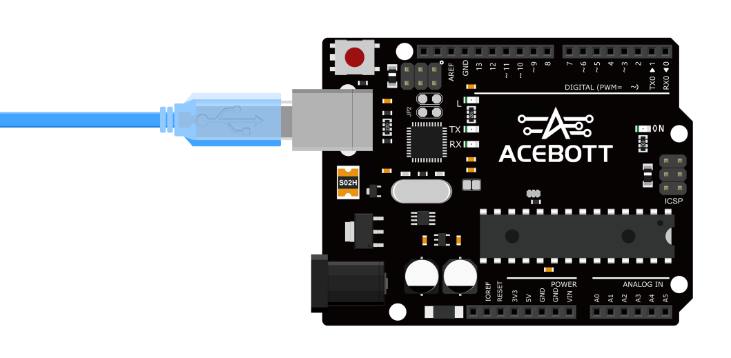
Connect the board to the computer using a USB data cable: Select “Arduino AVR Boards” -> “Arduino Uno” from the Tools > Board menu. Choose the appropriate Port. And upload it to the board using the Upload button.
(1)Wiring Diagram
(2)Sample Code
1void setup() {
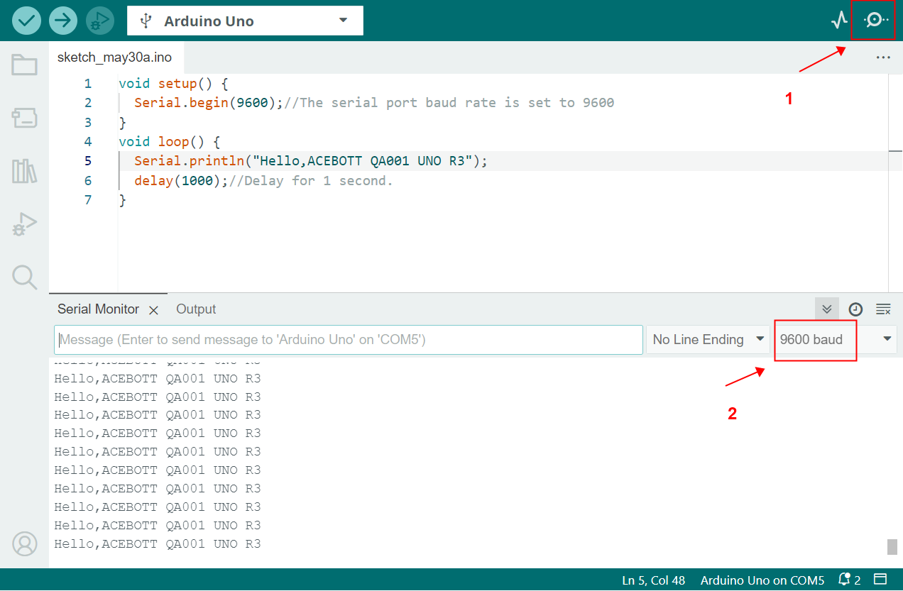
2 Serial.begin(9600);//The serial port baud rate is set to 9600
3}
4void loop() {
5 Serial.println("Hello,ACEBOTT QA001 UNO R3");
6 delay(1000);//Delay for 1 second.
7}
5.Test Result
After uploading the program, open the serial monitor in the Arduino IDE to observe the continuous serial printing of “Hello,ACEBOTT QA001 UNO R3”.
6.Related Resources
7.Get One Now
B2B Business: info@acebott.com