QB004 Potentiometer Module
1.Product Introduction
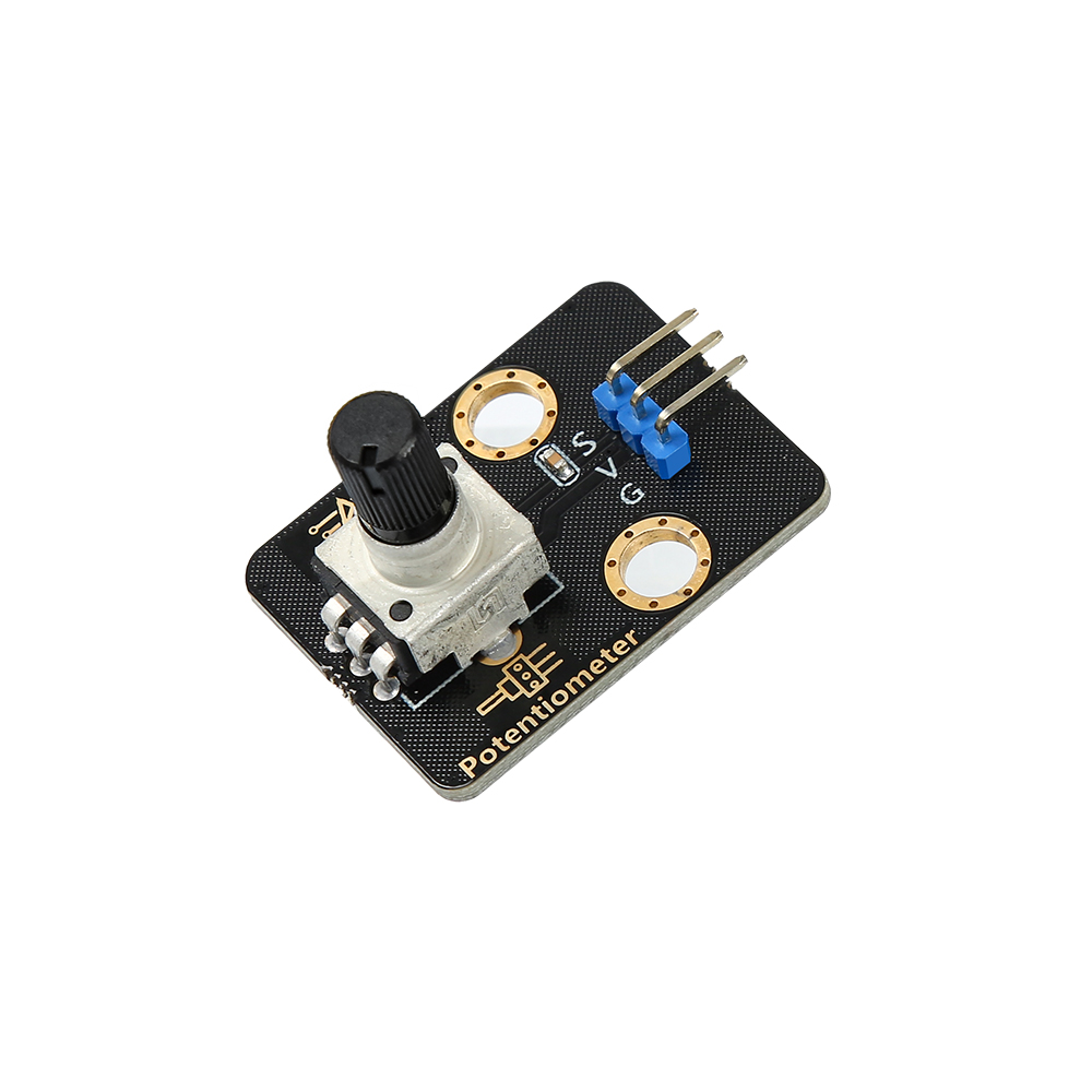
The potentiometer module is a linear rotating variable resistor with a maximum resistance of 10KΩ. We sense the state of the knob by detecting the voltage change caused by the change of its resistance, so as to control the movement of other modules.
The potentiometer module is composed of a circular shaft and a knob, which usually has three pins: two fixed terminals and a sliding terminal. When the knob rotates, it is equivalent to adjusting the position of the sliding terminal with respect to the two fixed terminals, which in turn changes the resistance of the module.
Application reference: volume regulator, fan speed regulator, brightness regulator and other scenarios that need to change the output module parameters.
2.Parameter Specification
Parameter |
Value//Description |
|---|---|
Operating voltage |
3.3V~5V |
Operating temperature |
-10°C~+50°C |
Output signal |
analog signal |
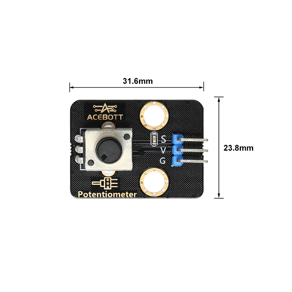
Size |
3.16cm*2.38cm |
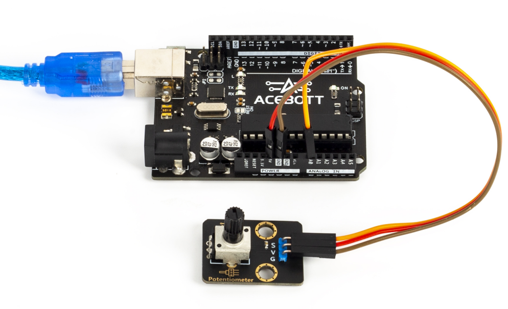
3.Wiring Diagram
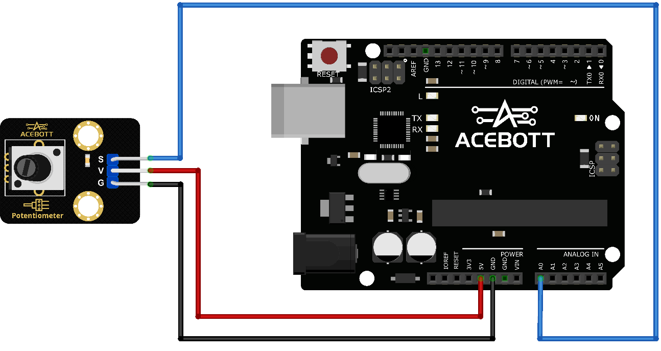
Potentiometer Sensor |
UNO |
|---|---|
VCC |
5V |
GND |
GND |
S |
Analog Pin A0 |
4.Sample Code
1//www.acebott.com
2void setup(){
3  pinMode(A0, INPUT);// Set pin A0 to input mode
4  Serial.begin(9600);//Set baud rate to 9600
5}
6void loop(){
7  Serial.println(analogRead(A0));// Read the state of pin A0and print it to the serial monitor
8  delay(1000);
9 }
5.Test Result
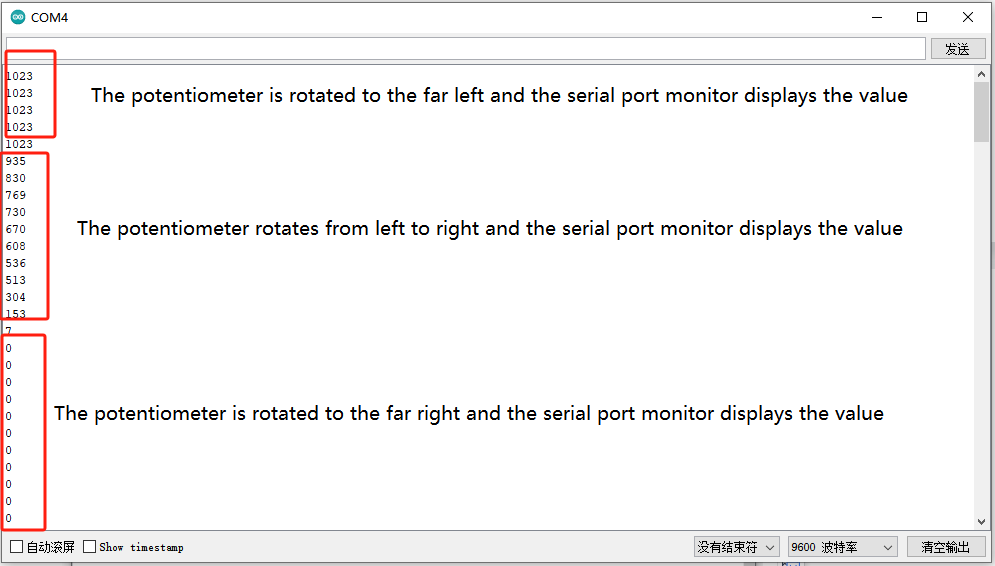
After uploading the code to the controller board, open the serial port monitor of the Arduino IDE and set the baud rate to 9600.
When we turn the knob, we will find that the value on the serial port changes between 0 and 1023.
6.Related Resources
7.Get One Now
B2B Business: info@acebott.com
Individual buyer: shop on aliexpress